Personal
Car Stuff
Extras
Variable Valve Control
Info adapted from an old website from 1998-2000 by Mark Wan and the MG BBS, sorry both original pages seem now to be obsolete. Some more info can be found at http://www.sandsmuseum.com/
The VVC concept was first designed and patented by the UK firm AE Ltd (Associated Engineering Group) in the early 1970's, but its execution in mechanical terms was designed and patented by Rover in the early 1990's as a means of expanding the range of cars capable of using the K Series engine. It was therefore designed before the MGF was developed as part of Rover's shelf engineering activity.
Several other manufacturers including Alfa-Romeo, BMW, Porsche and Honda have developed systems giving more control than a fixed camshaft. None give the range of control patented by Rover.
Rover introduced the VVC to the MGF in 1995. It provides continuously variable timing that improves low to medium rev torque delivery; and unlike cam-phasing VVT, it can lengthen the duration of valves opening (and continuously) to boost power.
Basically, VVC employs an eccentric rotating disc to drive the inlet valves of every second cylinder. Since an eccentric shape creates non-linear rotation, the valves opening period can be varied.
VVC has one draw back: since every individual mechanism serves 2 adjacent cylinders, a V6 engine needs 4 such mechanisms, and that's not cheap. V8 also needs 4 such mechanism, but a V12 version is impossible since there is insufficient space to fit the disc and drive gears between cylinders.
| Advantage: | Continuously variable timing and duration of opening achieve both drivability and high speed power. |
| Disadvantage: | Not ultimately as powerful as cam-changing VVT, because of the lack of variable lift; Expensive for V6 and V8; impossible for V12. |
| Who uses it ? | Rover 1.8 VVC engine serving MGF, Caterham and Lotus Elise 111S. |
Mechanism Details
In its simplest form, the VVC Mechanism speeds up and slows down the camshaft so that the length of time the inlet valves are open can be varied without the profile of camshaft changing. Although the drive to the VVC Mechanism is at a constant half engine (or crankshaft) speed, the camshaft velocity varies within each revolution in such a way as to maintain an average of half engine speed.
The heart of the MGF VVC lies just underneath the cam cover. The first obvious thing one sees is that the inlet camshaft is not a single casting as in most engines, but is in four sections. Inlet valves for cylinders 1 and 2 are controlled by lobes on a half cam-shaft driven by a VVC Mechanism (the most important components of which are two drive rings) at the front of the engine. Inlet valves for cylinders 3 and 4 are controlled by lobes on a half cam-shaft driven by a second VVC Mechanism (incorporating its own drive rings) at the rear of the engine, the drive for the latter is taken from the exhaust camshaft.
Each half camshaft is in two parts, an inner independent shaft and an external shaft on which the cam lobes are located. Each VVC Mechanism housing is machined to swiss watch standards and contains a pair of needle roller bearings.
The other thing one notices is a cast hydraulic control unit and next to it, two 1 square plastic coated solenoids. These are driven from the Engine Management System (EMS) and, through a spool valve, control shaft connected to the toothed control sleeve on the outside of each driving ring assembly. One of these half-inlet camshafts, that for cylinders 3 and 4 is shown as follows:
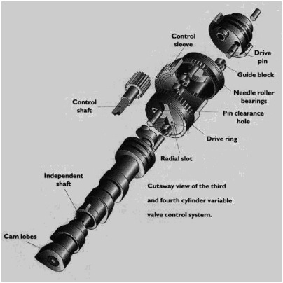
The really ingenious bit is the design of the VVC Mechanism. As the cross-sectional diagrams show, the outer control sleeve is machined such that it is much thinner on one side than the other, (i.e. it's bore is eccentric to it's outside diameter). The sleeve can be adjusted through about a quarter-turn which causes the pair of drive rings within the sleeve to move outside the camshaft's centre of rotation.
As the drive ring rotates within the sleeve, the camshaft drive pin moves from the inside of the radia slot to the outside, depending on whether the drive ring is at the thin side or the thick side.
A pin at the end of the external shaft slots into a hole in the face of the drive ring thus transferring the desired amount of movement to the external shaft and hence to the cam lobes.
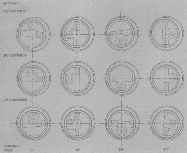
This picture shows exactly what happens within each revolution of the camshaft. If you examine the centre row of the diagrams, you can see that at the 260 degree cam period, the centre of the radial slot always revolves around the central axis. This ensures the drive pin (which transfers the movement to the external shaft on which the cam lobes are cast) stays in the centre of the pin clearance hole. In other words it performs as a normal fixed profile camshaft would.
The top and bottom rows shows the extremes of movement available. The drive pin is no longer always in the centre but can move clockwise or anti-clockwise to the edge of the pin clearance hole. The direction and amount of movement is determined by the extent to which the drive ring speeds up or slows down, relative to the input speed.
The top row of diagrams show the pin and radial slot in positions which allow the camshaft to open and close the valves faster thus allowing less fuel/air mixture in because less power is needed. In the bottom row, the valves are being opened and closed more slowly, thus allowing more time for more fuel/air mixture to be burnt, giving more power.
Having understood how it works, the next question is, how does the VVC mechanism know by how much to alter things as you drive along?
Information from the EMS MAP
In order to translate the mechanical system into the measurable performance effect described below, the EMS receives information on a continuous basis from non-contact sensors in several parts of the engine.
These tell it the current status of:
- Inlet cam position.
- Crankshaft rotation speed.
- Oil temperature in the hydraulic control unit.
- Inlet manifold air temperature and pressure.
- Coolant temperature at the top hose.
The difference between what the current status of each is and what the software inside the EMS has been programmed to decide the valve opening period needs to be at any particular fraction of a second, is then transmitted through the hydraulically controlled mechanical linkage of the VVC Mechanism to the camshaft lobes.
What is the effect?
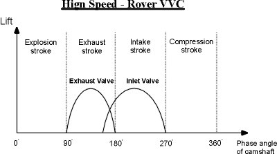
The software in the EMS ensures that the VVC Mechanism allows the length of time during which each inlet camshaft lobe permits each inlet valve to stay open, to be varied as the camshaft rotates. The amount of variation is huge - 75 degrees between 220 to 295 degrees, or about 40 degrees either side of the basic camshaft profile of 260 degrees if you prefer.
The amount of precision control is incredible. The EMS can map and if necessary alter, the degree of valve opening required within each single camshaft revolution.
To quote Laurence Pomeroy (The Grand Prix Car, published in two volumes in 1949 and 1954 ): Increased valve overlap (either side of top-dead-centre) and the extension of the total period of inlet valve opening contribute to increased effectiveness for a given valve area .
A Musical Analogy
If you take 1 bar of music, the underlying rhythm and hence the overall speed at which it is played can remain the same as hundreds of bars either side of that one. However a good instrumentalist (whether a string or wind player) can vary each note within one bar, and give clearly audible differences in phrasing.
This in its way, is what VVC does. It listens through the EMS sensors to the way you drive the car. The crankshaft rotates at a constant speed (i.e. constant rhythm), yet the inlet camshaft's rotate at variable speeds depending on the instructions given to it by EMS.
VVC's Benefits
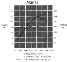
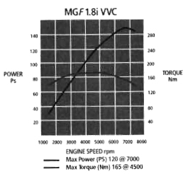
The system increases the power output from 120 PS to 145 PS. This additional 25 PS, is available over much more of the rpm range, giving more torque than the standard car. It also increases the maximum safe limit by 8% from 6750 to 7300 rpm.
The driveability of the car is drastically improved because the increased power is available between 4000 and 7000 rpm, which is what you need when accelerating hard to overtake that lorry.
Because the system enables the cam profile (and hence volumetric efficiency) to be accurately matched to the amount of welly you give the accelerator pedal, you use less fuel, probably by as much as 5% to 10% depending on your driving style and the journeys you take.